Motivation for this work
The principles of the Stirling engine are well known for a long time. The aim of this project is to propose simplified but still practical stirling engine designs that can be built by individuals without the use of advanced tools and materials. This document describes three Stirling engine designs, two of which were built and tested by the author himself. The third one is still work in progress, but is based on the knowledge and conclusions drawn from the two working prototypes and seems verypromising.
Before going into details, please note: I am not pretending that this work is noval, nor I intend to steal anybody's patent or intellectual work and property. And also, USE AT YOUR OWN RISK!!! HEAT ENGINES CAN BE DANGEROUS, IF NOT PROPERLY USED!!! ESPECIALLY EXPERIMENTAL ONES!!!
Construction idea
Efficient Stirling engines are not easy to build, because they use pistons which need to be properly sealed. Sealing while moving means friction and thus lubrication. Lubricants are mostly flammable should not be exposed to high temperatures, explosions may happen. Pistons are made of metal, metals extend while warming up, so some compensation mechanism like piston rings should be used, this makes the construction even more complicated.
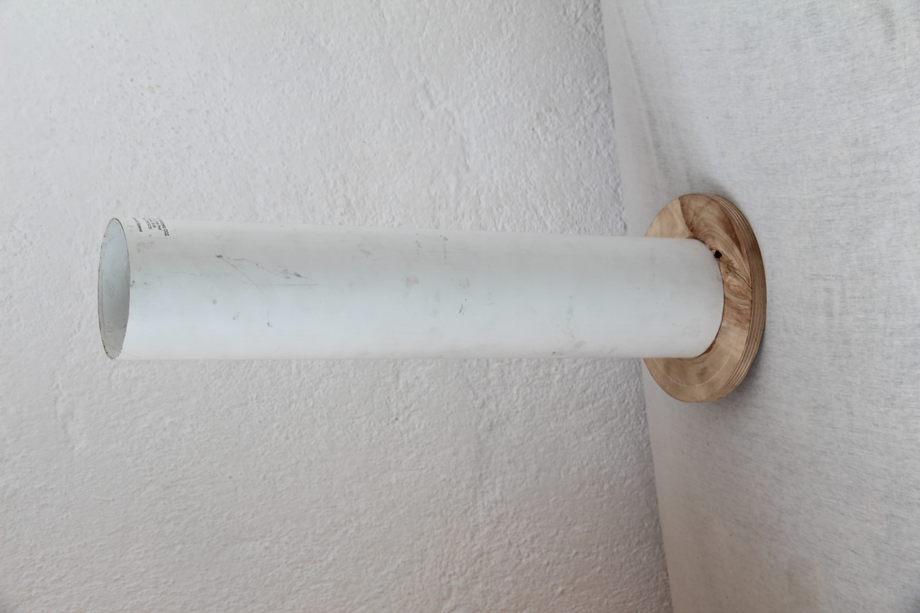
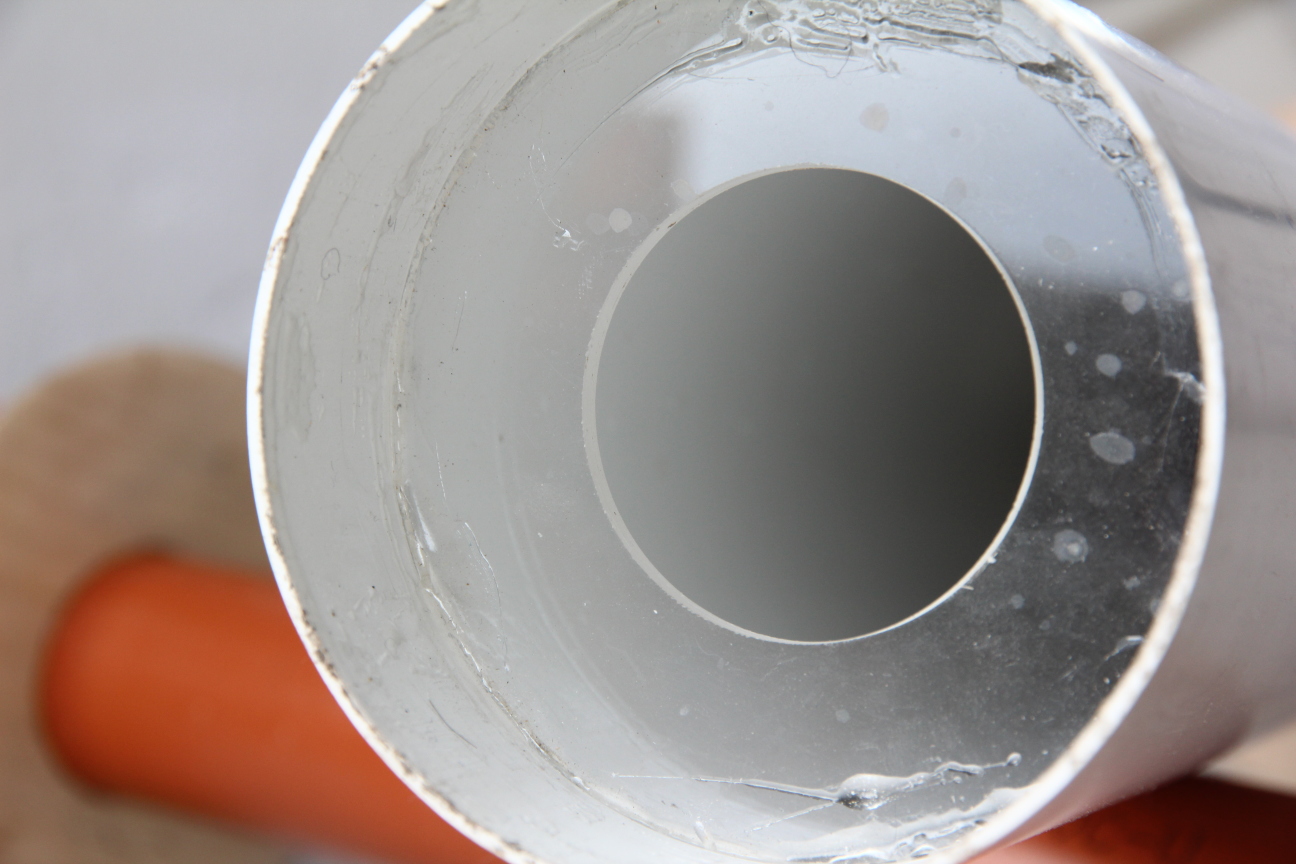
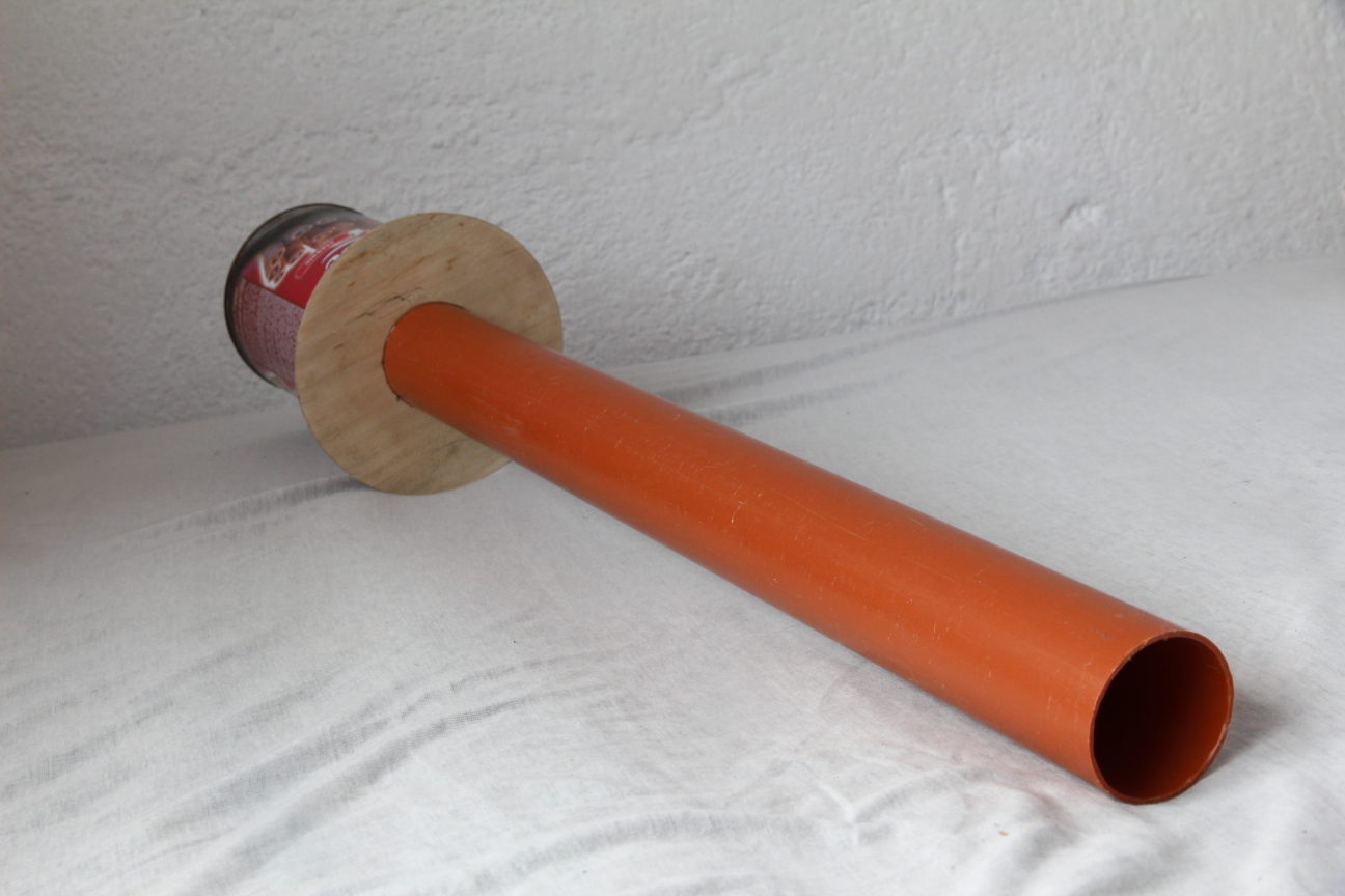
A radical way to avoid these problems is to use water as piston, perfect sealing, lubricant and coolant. Two working Stirling designs using water as a piston are shown on Figure 1. Both machines have a work cylinder opened at the lower end and placed in a base cylinder filled with water. At the top of the work cylinder the air can not escape and causes the work cylinder to swim. The vertical position of the work cylinder can be adjusted by adding/releasing air in the cylinder. Note that the height of the work cylinder may be chosen in such way, that the mass of the water inside the cylinder is much bigger than the mass of the cylinder itself. The work cylinder is positioned in the center of the base cylinder by the loose slide bearings. Such a bearing may be implemented simply as 3 nails that are orthogonal to the wall of the work cylinder. The bearings however are not required to seal perfectly. They should be close enough to assure straight movement. Since the work cylinder moves up/down, the friction forces acting there are very small, water acts as coolant and lubricant.
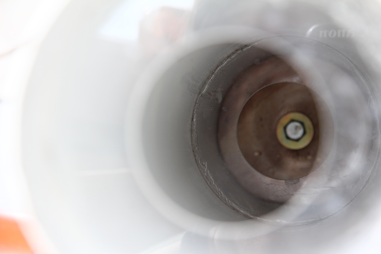
The main construction difference is that the left design uses a moving displacer which is attached to the work cylinder by a spring, while the right design uses a non-moving displacer which is attached to the bottom of the base cylinder by a stiff metal rod. The difference may appear small at first, but it has great impact on the behavior of the two engines. In the following sections the principles of operation are explained.
Principle of operation of the water piston Stirling engine with static displacer (WPSD)This is the more simple of the two designs. Heat comes from above. When the work cylinder rises, the cold air is pressed around the displacer upwards and is heated, so the pressure inside the work cylinder increases. This causes the cylinder to rise even more rapidly until it hits the displacer with the bottom of the wider part of the cylinder. Since the displacer is static, the work cylinder can not rise further. The pressure in the work cylinder then pushes the water down the pipe. At some point the pressure falls enough so that the work cylinder starts moving down. The hot is then pressed around the displacer downwards and is thus cooled. This again increases the pressure fall and the speed of the work cylinder until its top hits the top of the displacer. Then the water is sucked into the water cylinder until the pressure rises again enough to cause the work cylinder move upwards, and so on. Principle of operation of the water piston stirling engine with moving displacer (WPMD)The displacer is attached to the work cylinder by a spring, thus being a spring/mass system with a certain natural frequency. When heat comes at the upper end of the work cylinder and the displacer starts moving (e.g. by initial manual hit), the pressure in the working cylinder changes according to the position of the displacer in the cylinder. This pressure change acts on the water in the work cylinder. Assuming that the mass of the water in the work cylinder is bigger than the mass of the whole cylinder, the cylinder will move more intensively than the water, especially in higher frequencies. This movement is at the same frequency as the displacer movement, shifted at 90 degrees, so the displacer movement increases its amplitude. Note, that the frequency does not depend on the quantity of the water inside the work cylinder, it depends on the mass of the displacer and the spring value. |  Figure 1: Atmospheric water piston stirling engines -
|
Comparison of WPMD and WPSD
WPSD is simple to build, but has some drawbacks. The work cylinder hits the displacer to change direction, thus loosing energy. The losses can be lowered by inserting small springs at the end points, but this makes the construction more complicated. Also, the water is forced to move intensively, which causes fluid friction losses. To lower them, aerodynamic analysis is necessary, this is definitely not a simple task. The water movement also makes the frequency of the engine pretty low, since water is heavy.
On the contrary, the WPMD design does not rely on water movement. It instead uses the water as sealing, lubricant and reference mass. It works at higher frequency than WPSD and has much lower water movement amplitude. By properly adjusting the spring and the height of the water cylinder, the losses that occur in WPSD should be minimal.
One possible advantage of WPSD is the fact, that the pressure difference in low/high position in the work cylinder is much bigger as in WPMD. This is due to the abrupt stops of the work cylinder as well as due to the relatively big mass of the water that moves. The water is accelerated and then suddenly stopped, which causes sudden pressure rise/fall. This can be used to construct a simple pump by inserting a valved pipe through the bottom opening of the work cylinder. Similar principle is used in the hydraulic ram pump - http://en.wikipedia.org/wiki/Hydraulic_ram
Video comparison of WPSD and WPMD in action
What else needs to be done?Both of the proposed designs (WPMD and WPSD) are opened, atmospheric systems, which makes them bulky. A closed, pressurized system would produce more energy per volume unit. The work cylinder needs to be heated from above, which is not straightforward, since the work cylinder is moving. Another engine design, sketched in Figure 2 addresses these issues. The idea here is different as in the previous designs. While the displacer moves up and down, the pressure inside the closed system falls and rises. The air in the work cylinder tries to equalize its pressure to the pressure inside of the closed system, so it expands or shrinks. Thus the work cylinder moves up and down, giving feedback to the displacer via the spring. Note that while the work cylinder moves up, the displacer is pulled down. This is necessary to achieve oscillation. It is possible to construct other mechanisms to assure this, but for simplicity, this design uses a balancing rod. Some words on heat/coolant arrangementThe proposed designs always expect the heat to come from above. This assures, that air streaming losses can be minimized, since hot air rises and stays there, while cold air falls down. Also, water can not fly, so this is another reason to make the lower part cold and the upper one hot. Water helps to cool down the lower part of the system. Since it stays low, the upper part can be heated to very high degrees. According to the TD principles, the bigger the temperature difference, the higher the efficiency of the system. How to extract energy?The open systems can be used as pumps or as mechanical actuators. Electricity can be produced with linear alternator mechanisms. The closed system would be suitable for producing electricity |  Figure 2: Closed system water piston stirling engine |
Related work
This work is inspired by many other alternative stirling designs. Some of them use water instead of a solid piston,
e.g. http://www.alice-dsl.net/bsuhrbier3/index.html#Ecotic. However, the designs proposed here seem more capable of reaching high frequencies, do not rely on diaphragms, use simple cylinders as building blocks. The last design can be pressurized.
The WPMD design is very similar to the design proposed in http://superengine.de/e-resonanzfragen.html However, WPMD uses water and does not use wall deformation in order to achieve the resonant effect. This seems to be somewhat more reliable and simple to build. WPMD can be cooled by the water of the work cylinder.
The WPSD design is the most simple of the proposed designs and can be compared to the Manson engine http://manson-ericsson-hae.blogspot.com/p/ma.html, which features only one moving part. The WPSD design has however a stirling cycle and does not loose energy for pressure equalization at the endpoints. It thus should be more efficient than a manson engine.
Conclusion
These Stirling designs are developed as a hobby project which was a great fun, this alone justifies the time spent. The result of the project are two working prototypes, WPMD and WPSD, as well as a pressurized design which may be functional, based on the conclusions drawn from the two prototypes. The main goal was to make things as simple as possible, while not compromising the efficiency.
I hope that there will be enthusiasts who will find these designs interesting and will help to make them practical and useful. Or even better, I hope that this work could inspire other people to develop their ideas.